What is Ex 'D' solution?
Today, we delve into one of the oldest and widely adopted explosion-proof methods known as the Ex ‘d’ solution, commonly referred to as ‘Flameproof’.
In the realm of safeguarding lives and equipment in hazardous environments, various explosion-proof protection methods are employed today, including Ex ‘i’ (Intrinsically Safe), Ex ‘e’ (Increased Safety), Ex ‘nR’ (Non-sparking), and more. Among these, Ex ‘d’ Flameproof stands out. To explore diverse explosion-proof protection techniques, you can refer to our comprehensive article on the subject by clicking here.
The Ex ‘d’ method operates on a fundamental principle: ‘To separate the hazardous environment from ignition sources’ such as flames and hot gases.
This method is precisely defined in IEC 60079-1. In the regulatory landscape, the seventh edition of IEC 60079-1 further categorizes it into Ex ‘da,’ Ex ‘db,’ and Ex ‘dc’ for EPL Ga, Gb, and Gc, respectively.
For simplicity in this discussion, we will use ‘Ex db’ interchangeably with ‘Ex d,’ clarifying that our focus remains consistently on the context of EPL Gb.
How it works?
 As mentioned earlier, Ex ‘d’ method is based on the principle of separation of hazardous environment from ignition sources. An Ex ‘d’ enclosure is made in such a way that it can contain the pressure developed due to explosion happens inside the enclosure, and also it quench the hot gas, flames that comes outside of the enclosure from the joint gaps, threads etc. due to the explosion.
When pressure changes due to fluctuations in temperature and atmospheric pressure flammable gases or vapors in the surrounding area can enter the enclosure through the joints, creating an explosive mixture. The design assumes that the explosive mixture of gas or vapor will fill the enclosure during normal operation. Many types of electrical equipment produce arcs or sparks which have enough energy to ignite this hazardous gas or vapor. If it is ignited by the electrical equipment the enclosure is built to withstand the pressure of the explosion without rupturing and without transmitting the explosion to the surrounding atmosphere through its joints. An enclosure is usually made of a cast metal alloy the thick walls ensure that the enclosure will withstand the force of an internal explosion, and the joints are either threaded or machined flat to create a controlled flame path which prevents an explosion of the surrounding atmosphere. The metal surfaces absorb and conduct away some of the heat. There is also additional cooling of gases as they mix with the cooler atmosphere outside the enclosure. All hazardous location enclosures are carefully designed to strict standards that include large safety factors. The manufacturing process starts with the pouring of a casting and during machining particular care is taken to ensure that the joints are flat smooth and free from defects entries and carefully drilled and tapped. Every joints and entries and threaded joints is tested to ensure that it can hold pressure and contain an explosion.
Field Modification of Ex ‘d’ Equipment
Flameproof enclosures are normally supplied complete with all internal components fitted and certified as a single entity by a recognized test authority. The testing procedure will take into consideration the free internal volume after all the components have been fitted, the temperature rise,
creepage and clearance distances and the rise in pressure as a result of an internal explosion using a gas/air mixture in its most explosive proportions. Replacement components should be the same as the original components. For example, a component larger or smaller than the original will affect the internal geometry of the enclosure. Pressure piling is a possibility if a larger component is fitted and increased volume will result if a smaller component is fitted. Drilling and tapping of the entries should only be carried out by the manufacturer of the enclosure or his approved agent. The threads of the entries are required to be compatible with those of the cable glands or conduit in terms of type of thread, thread pitch and clearance tolerance since flamepaths exist at these points. Gaskets can only be replaced, they must not be added retrospectively if not included as part of the original design.
Ex d – Flameproof: 3 types of joints

Flanged designed enclosures are not designed for IIC applications. However, you can find certain flanged enclosures suitable for IIB+H2. Threaded Joints and Spigot Joints are specifically for IIC gas groups.
Weatherproofing Ex ‘d’ Equipment
In general, the use of Ex ‘d’ flameproof equipment without the use of gaskets or seals will only provide protection up to IP54. For applications requiring higher levels of IP protection, the use of gaskets integrated within the flamepath is a common option to consider. Other weatherproofing materials considered and commonly used are nonhardening grease bearing textile tape in the UK and non‐setting grease or compounds. The use of non‐setting grease on machined surfaces of flamepaths has two advantages since in addition to providing an additional level of ingress protection, it also inhibits the formation of rust on these surfaces. Silicone based greases require careful consideration in order to avoid possible damage to the elements of gas detectors. In general, consult with the manufacturer of Ex ‘d’ equipment for recommendations involving lubricants and tapes to be sure.
Obstruction of Flamepath
A solid obstruction such as a wall, steelwork, conduit, brackets or weatherguards or other electrical equipment in close proximity to the opening of the joint can, in the event of an internal explosion, reduce the efficiency of the flamepath to the extent that ignition of the external gas or vapor could occur. Minimum distances between the flamepath opening and an obstruction as specified in IEC 60079‐14

Ex ‘d’ Flameproof Conduit Systems
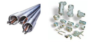
 Although, conduit is not widely used in Northern Europe, this technique is included in the CENELEC standard and the IEC standards as one of the entry methods into flameproof enclosures. The design and testing requirements are contained in the CENELEC and IEC Standard IEC 60079‐1. Either tapered (NPT) or parallel (straight or metric) threads are acceptable. The conditions are:
- The Ex d enclosure must be certified.
- Only the manufacturer can make the drilled and tapped entries into the Ex d enclosure.
- All conduits or cable glands entering the enclosure must be sealed by an approved method.
From the area beyond the enclosure seal, all of the wiring methods and fittings are considered installation materials and not subject to any certificate or approval. Thus, getting fittings certified to the ATEX directive would not be a common practice. The correct use of conduit installation is spelled out in the installation standards EN 60079‐14 and IEC 60079‐14.
How it's tested?
An explosion-proof window is installed to allow you to see the explosion inside the enclosure. An explosive gas air mixture is piped in and a spark plug is used to ignite it. This is followed by a water pressure test in which the enclosure is subjected to a pressure of 1.5 times the maximum explosion pressure.
Another test is performed to confirm that the joints will prevent an ignition of the surrounding atmosphere. In this test the enclosure is surrounded by an explosive gas mixture inside a plastic tent note that the internal explosion is not transmitted to the outside explosive mixture. Then deliberately damage the flange joint to demonstrate what can happen if there is an explosion with a damaged flame path. To protect the machine joints covers must be handled carefully so that they are not damaged or dropped cleaning the joints ensures. There will be no dirt in the joint to prevent it from closing properly a thin layer of grease can be used on a flat joint to protect against corrosion and on a threaded joint for corrosion protection and to guard against binding of the threads some joints also contain O-ring seals to prevent moisture from entering the enclosures. When they are used in outdoor locations make sure they are properly seated if a joint becomes accidentally painted or corroded clean the joint with a solvent and a clean rag or attempt to remove the paint or corrosion by filing or scraping this could damage the joint if necessary the enclosure should be sent out for repair or be replaced and of course all bolts must be installed and tightened to maintain strength and flame path integrity. A good precaution is to check all flanges with a feeler gauge and threaded covers must be fully engaged installation and maintenance instructions are provided with hazardous location equipment. They contain a lot more information than we’ve been able to cover now the instruction sheets and labels on equipment are there to help you every time you install or maintain a hazardous location device remember all the care and attention that went into its design and manufacture make sure that you are doing your part to keep it safe.


